How To Calculate Current In Circuit
News Co
Apr 06, 2025 · 6 min read
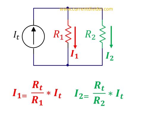
Table of Contents
How to Calculate Current in a Circuit: A Comprehensive Guide
Calculating current in a circuit is a fundamental concept in electronics and electrical engineering. Understanding how to do this accurately is crucial for designing, troubleshooting, and maintaining electrical systems. This comprehensive guide will explore various methods for calculating current, covering both simple and complex circuits, and equipping you with the knowledge to tackle a wide range of problems.
Understanding Basic Electrical Concepts
Before diving into the calculations, let's refresh some fundamental electrical concepts:
1. Current (I):
Current is the rate of flow of electric charge. It's measured in amperes (A), often shortened to "amps." Imagine it like water flowing through a pipe; the amount of water flowing per second is analogous to the current.
2. Voltage (V):
Voltage, also known as potential difference, is the electrical pressure that drives the current. It's measured in volts (V). Think of it as the water pressure in our pipe analogy; higher pressure means more water flows.
3. Resistance (R):
Resistance is the opposition to the flow of current. It's measured in ohms (Ω). In our analogy, this is like the friction within the pipe; higher friction means less water flows.
4. Ohm's Law: The Foundation of Current Calculation
Ohm's Law is the cornerstone of electrical circuit analysis. It states that the current (I) flowing through a conductor is directly proportional to the voltage (V) applied across it and inversely proportional to its resistance (R). Mathematically, it's expressed as:
I = V / R
This simple equation allows us to calculate the current if we know the voltage and resistance.
Calculating Current in Simple Circuits
Let's start with the simplest scenario: a circuit with a single resistor connected to a voltage source.
Example 1: A Single Resistor Circuit
Imagine a 12-volt battery connected to a 4-ohm resistor. To calculate the current:
- Identify the known values: V = 12 V, R = 4 Ω
- Apply Ohm's Law: I = V / R = 12 V / 4 Ω = 3 A
- Result: The current flowing through the circuit is 3 amperes.
Example 2: Different Voltage and Resistance
Let's consider a circuit with a 9-volt battery and a 1.5-ohm resistor. Following the same steps:
- Known values: V = 9 V, R = 1.5 Ω
- Ohm's Law: I = V / R = 9 V / 1.5 Ω = 6 A
- Result: The current is 6 amperes.
Calculating Current in Series Circuits
In a series circuit, components are connected end-to-end, forming a single path for the current. The current remains the same throughout the entire circuit.
Calculating Total Resistance in Series Circuits
To calculate the current in a series circuit, we first need to find the total resistance (R<sub>T</sub>). This is simply the sum of the individual resistances:
R<sub>T</sub> = R<sub>1</sub> + R<sub>2</sub> + R<sub>3</sub> + ...
Example 3: Series Circuit Calculation
Consider a series circuit with a 10-volt battery, a 2-ohm resistor, and a 3-ohm resistor.
- Total Resistance: R<sub>T</sub> = 2 Ω + 3 Ω = 5 Ω
- Apply Ohm's Law: I = V / R<sub>T</sub> = 10 V / 5 Ω = 2 A
- Result: The current flowing through the entire circuit is 2 amperes. This same 2A flows through both the 2-ohm and 3-ohm resistors.
Calculating Current in Parallel Circuits
In a parallel circuit, components are connected across each other, providing multiple paths for the current to flow. The voltage across each branch is the same, but the current divides among the branches.
Calculating Total Resistance in Parallel Circuits
Calculating the total resistance (R<sub>T</sub>) in a parallel circuit is slightly more complex. For two resistors, the formula is:
1/R<sub>T</sub> = 1/R<sub>1</sub> + 1/R<sub>2</sub>
For more than two resistors, the formula generalizes to:
1/R<sub>T</sub> = 1/R<sub>1</sub> + 1/R<sub>2</sub> + 1/R<sub>3</sub> + ...
Once R<sub>T</sub> is calculated, you can find the total current using Ohm's Law.
Example 4: Parallel Circuit Calculation
Let's say we have a 12-volt battery connected to two resistors in parallel: a 6-ohm resistor and a 3-ohm resistor.
- Total Resistance: 1/R<sub>T</sub> = 1/6 Ω + 1/3 Ω = 1/2 Ω. Therefore, R<sub>T</sub> = 2 Ω.
- Total Current: I<sub>T</sub> = V / R<sub>T</sub> = 12 V / 2 Ω = 6 A
- Branch Currents: The current will split between the branches. Using Ohm's Law for each branch:
- I<sub>1</sub> (through the 6-ohm resistor) = 12 V / 6 Ω = 2 A
- I<sub>2</sub> (through the 3-ohm resistor) = 12 V / 3 Ω = 4 A
- Verification: Notice that I<sub>1</sub> + I<sub>2</sub> = 2 A + 4 A = 6 A, which equals the total current I<sub>T</sub>.
Kirchhoff's Laws for More Complex Circuits
For more complex circuits that involve multiple voltage sources and interconnected loops, Ohm's Law alone is insufficient. We need Kirchhoff's Laws:
1. Kirchhoff's Current Law (KCL):
KCL states that the sum of currents entering a junction (node) in a circuit equals the sum of currents leaving that junction. This is based on the conservation of charge.
2. Kirchhoff's Voltage Law (KVL):
KVL states that the sum of the voltage drops around any closed loop in a circuit equals zero. This is based on the conservation of energy.
Solving complex circuits often involves setting up a system of simultaneous equations using both Ohm's Law and Kirchhoff's Laws. This requires a more advanced understanding of circuit analysis techniques, such as mesh analysis or nodal analysis. These methods are beyond the scope of this introductory guide but are crucial for mastering circuit analysis.
Practical Considerations and Troubleshooting
- Measuring Current: Current is measured using an ammeter, which must be connected in series with the component you want to measure.
- Circuit Breakers and Fuses: These safety devices protect circuits from excessive current.
- Short Circuits: A short circuit occurs when there's a low-resistance path between two points of different potential. This can lead to dangerously high currents.
- Open Circuits: An open circuit occurs when the path for current flow is interrupted. This results in zero current.
Advanced Techniques and Software
For more complex circuits, you may need to utilize advanced circuit simulation software such as LTSpice, Multisim, or similar tools. These tools allow you to model circuits, analyze their behavior, and perform simulations to predict current flow under various conditions. They are incredibly useful for verifying your calculations and exploring the impact of different components and configurations.
Conclusion
Calculating current in a circuit is a fundamental skill for anyone working with electronics or electrical systems. This guide has covered the basics, from Ohm's Law and simple series/parallel circuits to the application of Kirchhoff's Laws for more complex scenarios. Remember that a solid understanding of these concepts, coupled with practice, is key to mastering circuit analysis. Don't hesitate to explore advanced techniques and simulation tools as your skills develop, enabling you to tackle increasingly challenging circuit designs and troubleshooting tasks with confidence. Remember safety first when working with electrical circuits! Always exercise caution and follow appropriate safety procedures.
Latest Posts
Related Post
Thank you for visiting our website which covers about How To Calculate Current In Circuit . We hope the information provided has been useful to you. Feel free to contact us if you have any questions or need further assistance. See you next time and don't miss to bookmark.